For the optimum result of trap applications following points shall be noticed;
1- Application area
2- Differential pressure
3- Condensate flow rate (kg/h)
4- Capacity diagram of the manufacturer
1- Application Area
Best type or the alternative type shall be chosen from the trap selection table.
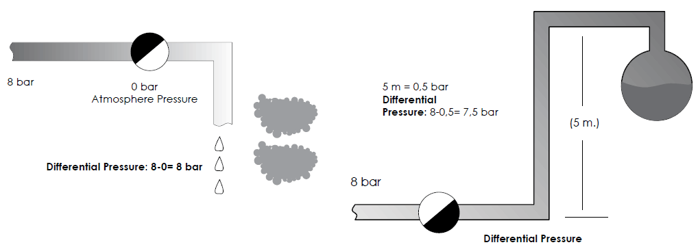
2- Differential Pressure
Differential pressure is the difference between steam trap inlet pressure and outlet pressure. For example; if the inlet pressure is 8 bar and the steam trap discharges to the atmosphere, differential pressure is 8-8=0 bar. After steam trap, each meter of elevation of the pipeline equals 0,11 barg back pressure. If in the previous example, condensate line elevates 5 meters after the steam trap, Back pressure is: 0,11x5: 0,55 bar So, the differential pressure is: 8-0,55=7,45 bar If the condensate is connected different condensate lines, total back pressure is to be calculated and steam trap selection is done accordingly.
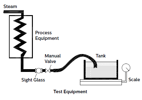
3- Condensate Flow Rate
Usually, the information provided by the machine manufacturer is accepted. Flow rate is indicated in the machine technical specifications. If this information is not reachable, it could be calculated according to process information (steam inlet diameter, flow density, etc…) Also, if it is not a special process, typical machine steam consumptions are given in the tables.
4- Capacity Diagrams
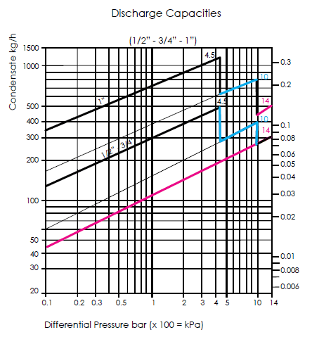
Capacity diagrams of Ayvaz float type steam traps SK-51 and SK-55 are given below.
Example for SK-51
For the steam trap, condensate flow rate is given 180 kg/h from the heat exchanger at 6 bar, condensate is discharged under 0,2 bar back pressure.
| Differential Pressure | 6-0,2 =5,8 bar |
| Condensate Rate | 180x3 = 540kg/h |
| Safety Factor | 3 |
1” (DN 25) sized steam trap which has 540 kg/h condensate discharge capacity at 5,8 bar differential pressure, indicated with blue line and number “10” in the diagram (steam trap capacity : 700 kg/h) is selected. “10” represents the steam trap orifice number. From the diagram, 1/2” and 3/4” sized steam traps are below the condensate capacity.
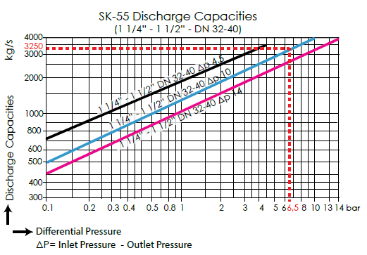
Example for SK-55
Condensate flow rate is given 1200 kg/h, steam trap is to discharge from 10 bar to condensate tank at 3,5 bar. 1 1/4” (DN 32) sized steam trap which has 2400 kg/h condensate discharge capacity at 6,5 bar differential pressure, indicated with blue line and number “10” in the diagram (steam trap capacity: 5000 kg/h) is selected. “10” represents the steam trap orifice number.
C- STEAM TRAP SIZING CRITERIAS
a) Steam trap inlet pressure must define exactly. If there are steam equipment before the steam trap, inlet pressure should accept as 15% under the main line pressure.
b) Back pressure must calculate. Each meter of elevation of the pipeline equals 0,11 bar back pressure.
c) Differential pressure must calculate.
Differential pressure = Steam Trap Inlet Pressure – Back Pressure
d) Condensate amount must calculate with the manufacturer information.
e) Safety factor must be apply to the condensate rate. Condensate Amount at main steam lines, heat exchangers and similar equipment, it is accepted as 2,5 to 3 times. For other equipment, it is 1,5 to 2 times.
f) After applying the safety factor to the condensate rate, according to condensate amount, the steam trap size must calculate from the manufacturer’s diagrams.